Load and haul efficiency does not stop with haul truck cycle times and tonnage yields; transitioning can also make or break an operation’s momentum. Todd Swinderman of Martin Engineering talks more about new concepts to execute effective trough transitions in a short distance.
When observing the conveyor transition points throughout an operation’s bulk handling system, the issue of dust and spillage is quite common and can have many causes.
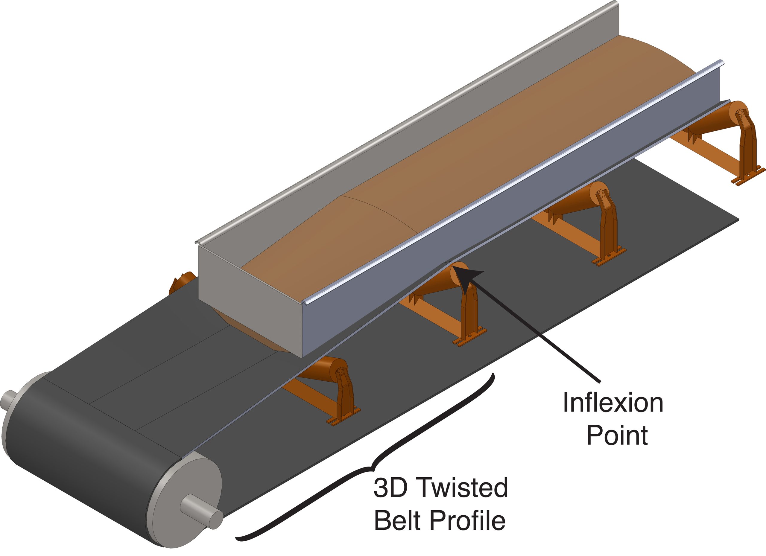
If spillage is observed piling behind the system, fouling the tail pulley, or becoming entrapped between the belt and skirt, it could be an indicator of “Loading on the Transition,” as seen in Figure 1. This is when a conveyor belt is loaded before it is in the fully troughed position, which is generally considered bad practice.
The belt in transition is a three-dimensional surface, and there is an abrupt inflection in the skirtboard angle at the first full trough idler, making it difficult to seal the belt in the transition. This difficulty in achieving an adequate seal results in the escape of fugitive materials.
The abrupt change in angle creates an entrapment point at the inflection that collects fine material, leading to belt grooving and leakage, which causes other problems such as seized rollers.
Despite these drawbacks, limitations imposed by a lack of available space and the maximum incline angle for a given material often motivate bulk handlers to accept loading on the transition to reduce a conveyor’s overall length. Others, in the misguided belief that an initial low price is more important than lower long-term costs, look for ways to shorten the conveyor even when not necessary.
Unfortunately, operations pay for this decision in many other ways, including increased equipment maintenance, additional cleanup time and potential safety hazards from personnel working in close proximity to the moving belt, as well as long-term health risks from poor air quality due to airborne dust.
If a workable solution to loading on the transition could be found, it would open up a large market for retrofitting older conveyors. However, due to space restrictions and material flow issues, older conveyors often can’t be re‐engineered to load after the belt is fully troughed allowing the retrofit design achieve a lower cost of operation.
A new, patented concept has been developed to execute an effective trough transition in a short distance. This new approach is based on a two-stage transition, with the first going from the tail pulley to a 20-degree angle, and then the full loading zone gradually transitioning from 20 degrees to the full trough angle at the exit, as seen in Figure 2. As a result, operators could obtain several benefits, including loading close to the tail pulley, the ability to modify chute angles, reduced skirtboard grooving and a transfer point that can be effectively sealed.
Transition distance
The transition distance is typically calculated based on the standard DIN 22101, which limits the edge stress of the belt as it goes from flat to troughed. The standard includes a minimum transition distance calculation based on the vertical rise of the belt on the wing roll of the target troughing angle compared to the top of the tail pulley. This is the reason many installations use partial troughs to raise the tail pulley, shortening vertical rise transition distance without exceeding the allowable edge stress.
Another approach to shortening the transition is to lower the tail pulley, which can pinch the belt between the idler roll gaps. However, these techniques are not without their own problems, including idler junction failure, belt buckling and the belt rising off the idlers; all can lead to belt damage.
With a traditional transition, the belt is twisted from a flat profile at the tail pulley to a troughed profile. This creates a 3D complex surface on the wing portions of the belt and makes it impossible to offset a straight‐bottomed skirtboard and wear liner parallel to the belt surface.
Designers often use adjustable transition idlers constructed with three equal roll idlers and adjustable wing outer brackets in an attempt to create a straight belt line under the skirtboards in the transition. This practice does not create a flat belt line, nor does it eliminate the inflection point, also showing in Figure 3. In fact, it often creates multiple inflection points.
In attempts by every maintenance shift to “tweak” the wing angles and reduce spillage and belt wear, the transition can quickly get so far out of adjustment that the problems are often made worse.
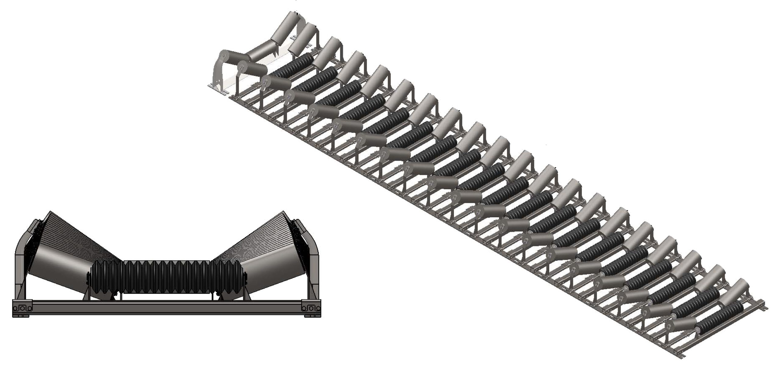
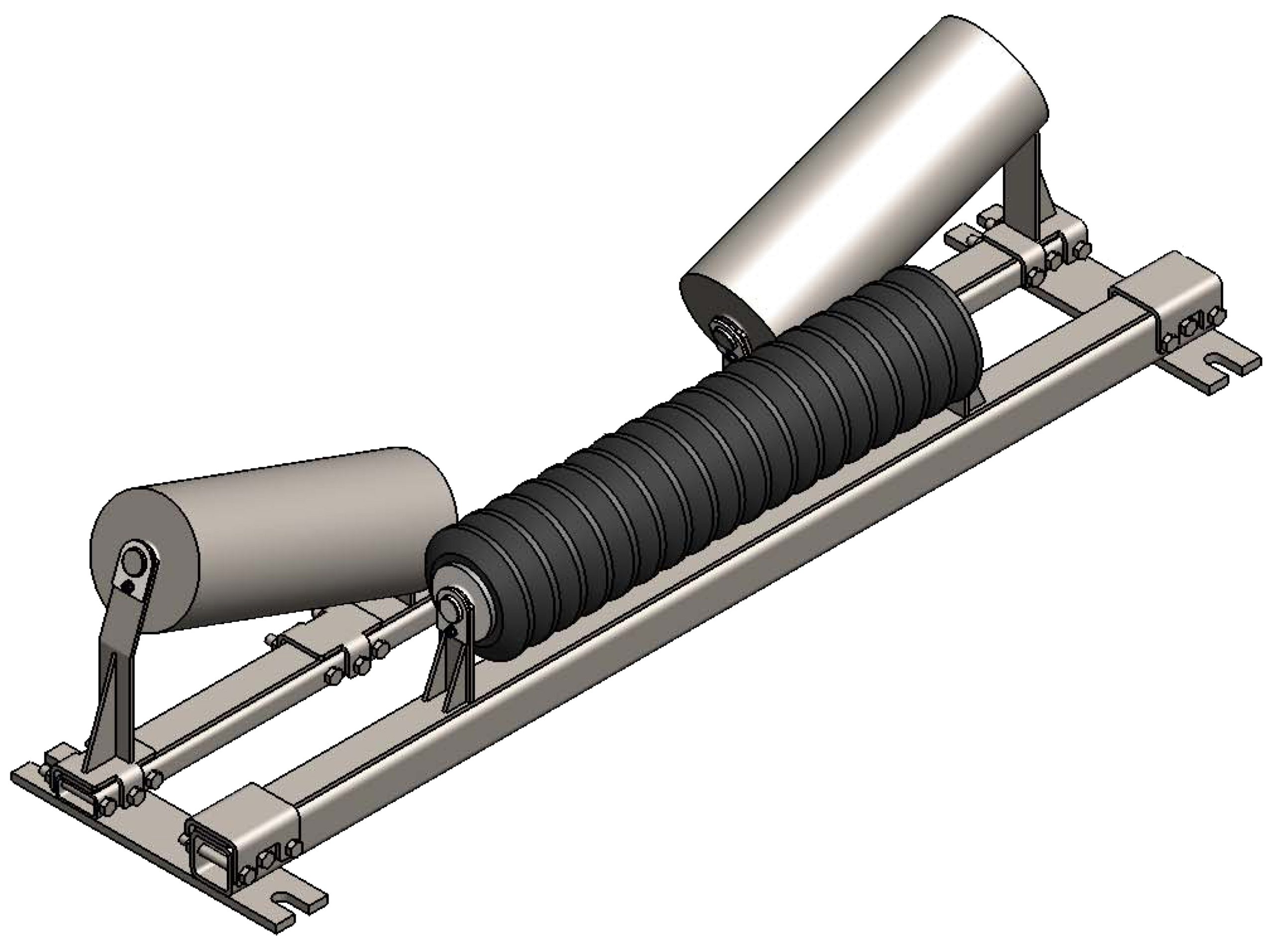
A new solution is to transition the belt to a picking idler profile, with the length of the center roll of the picking idler approximately the width the skirtboards are spaced. A second transition from the picking idler to a conventional three equal roll troughing idler is constructed by gradually changing the wing roll angle and wing roll center bracket height. With this approach, the belt is gradually transitioned through the loading zone to a conventional troughing idler at the end of the loading zone.
By transitioning first to a picking idler profile, the transition distance is dramatically shortened. The second transition can be engineered so the belt surface under the skirtboards is a straight line controlled by gradually increasing the trough angle and idler wing roll center bracket height, as seen in Figure 4. Fugitive material release is significantly reduced, and the inflection point is eliminated, along with the belt damage it causes. Proper skirtboard and wear liners can be installed, and sealing technologies can be applied effectively.
Among the perceived disadvantages of the picking transition loading concept is that each application would require custom engineering. Each idler will need either a special frame or a frame that can be engineered with adjustable angles and roll support heights to handle most applications. This disadvantage is minimized by using standard rollers in the custom frames.
For those who have no choice but to live with loading on the transition and the problems it creates, the cost of engineering and fabrication will be easily offset by reducing belt damage and minimizing fugitive material.
The ultimate objective is to build a second transition section that extends the length of the transfer point, transitioning from 20 degrees to the final trough angle and creating a flat belt surface over the wing rolls to which a skirtboard with a straight bottom can be spaced parallel to the belt, as shown in Figure 5.
Design process
The basic design criteria for a two-stage picking transition are:
- The exposed portion of the center roll of the 20-degree picking idler in the first transition is made equal to the chute width.
- The first transition from the tail to 20 degrees is governed by DIN 22101 transition design formulas.
- The second transition starts at a 20-degree wing angle and the wing angle incrementally increases to the exit of the load zone at the final design trough angle (i.e. 30, 35 or 45 degrees).
- The center rolls are all the same length, and the wing rolls
are all the same length. As the second transition progresses, more and more of the wing rolls are exposed until the configuration is the equivalent of the final design troughing idler angle and roller/belt contact. - The center roll height is the same as the final design troughing idler center roll. The inside brackets of the wing rollers are gradually increased as the wing angle increases to create the flat belt line under the skirtboards.
- The number of idlers in the second transition is determined by the idler spacing. The wing angles are increased in equal steps based on the number of idlers.
- The last idler in the loading zone is a conventional three equal roll troughing idler of the final design trough angle.
Step 1
The nominal skirtboard width should be determined, based on a de-rated design capacity, belt width and the final belt trough angle in the carrying zone. It’s recommended the skirtboard width be determined by the amount of free belt edge required for an effective sealing system installation and the expected belt wander.
According to Foundations 4, the free edge distance is at least 115 millimeters (4.5 inches) regardless of belt width, which includes 50 mm (2.0 in.) of expected belt wander[1], as showing in Figure 6. If more belt wander is expected, the free edge distance in the load zone should be increased. This distance should not be confused with the DIN or CEMA standard belt edge used in determining the design capacity of the carrying idlers outside the load zone.
Step 2
Determine the length of the transfer point. The first transition to 20 degrees is determined by the DIN 22101 formulas and generally requires only one specially designed 20-degree transition idler.
The second transition length is based on the need for: dust control, reducing material slip-back, controlling the turbulence of the material or other requirements of the application. An additional consideration may be the need to increase the chute angle for better material flow. Generally, the need for dust control will govern the length of the second transition, therefore the second transition length equals tailbox + loading section + skirtboard extension (two seconds of belt travel times the belt speed for dust control is recommended for the extension).
Step 3
The final step is determining the idler spacing in the second transition, with a minimum of 330 mm (13 in.), based on the current picking idler design for 125-mm (5-in.) and 150-mm (6-in.) diameter rolls, and designing the custom idler frames. By dividing the length of the transfer point by the idler spacing, the required number of idler sets can be calculated, with the last troughing idler being a standard three equal roll idler. The wing roll angles are in equal increments based on the spacing.
If variable spacing is used, it is recommended that it be a multiple of 330 mm (13 in.). For example, 330-mm (13-in.) spacing in the impact area and then 660 mm (26 in.) for the rest of the second transition.
The design of the wing roll brackets involves applying geometry to determine the heights of the wing roll brackets to create the flat belt line under the second transition skirtboards. This is done by creating an imaginary trapezoidal surface with the two bases equal to the belt contact line on the first and last wing rolls in the second transition.
Using 3D modeling, the height of the wing brackets necessary to create contact with the imaginary surface and create a straight belt line under the skirtboards can be determined. The result is each wing idler bracket in the second transition will be a unique design (but the rollers are all identical). The center roll is always the same length, and the bracket is always the same as the first transition picking idler.
Example
A 1200-mm (48-in.) fabric belt running at 2 meters/second (400 feet per minute) and between 60-90% of rated belt tension may require only a 600 mm (24 in.) first stage picking transition before the tailbox and load chute begin. The second transition is 4 m (13 ft.) long plus the length of the load chute to accomplish the two seconds of belt travel after loading needed for passive dust control, as seen in Figure 7.
Completing the transition zone
Once the transition zone has been designed, the remaining conventional components can be put in place. Typical additions are engineered sealing systems, increased skirtboard enclosure height and dust curtains for passive dust control or air cleaners for active dust control.
Conclusion
The two-stage picking transition offers many benefits:
- Shortened conveyor length reduces construction costs on new installations.
- Existing conveyors can be retrofitted to reduce belt damage and spillage.
- Chute angles can be increased to reduce flow problems.
- The load profile deepens as the material flows through the load zone, reducing pressure on the skirt walls to minimize chute plugging, wear and spillage.
- The individual idlers on custom frames can be removed from the side without lifting the belt.
- The offset picking idler design reduces idler junction failure.
- Replacement rollers are of standard design.
Precision Pulley and Idler (PPI) engineers each set of picking idlers based on the trough angles and transfer point length, using CEMA idler load calculation methods. Martin Engineering engineers, installs and maintains the containment elements of the transfer point.
The added cost of the idler frames is estimated to be approximately 35% more than a conventional offset idler frame. In new construction, the cost is offset by having a shorter belt center distance. On retrofits, the cost is quickly recovered by reduced belt damage from skirtboard seal grooving and reduced cleanup costs.
References
1) Foundations: The Practical Resource for Cleaner, Safer, More Productive Dust & Material Control (Fourth Edition), Todd Swinderman, Andrew Marti, Larry Goldbeck, Daniel Marshall & Mark Strebel, Copyright Martin Engineering, 2009.
About the author: R. Todd Swinderman is president emeritus of Martin Engineering. He has been with the company’s conveyor products division in 1979, subsequently serving as vice president and general manager, president, CEO and chief technology officer. Swinderman retired from Martin Engineering to establish his own engineering firm, currently serving the company as an independent consultant.