A conveyor belt is only as good as its design, and then only as good as it is maintained. Superior Industries’ chief conveyor engineer Travis Thooft outlines vital design considerations allowing successful maintenance.
Dry bulk material producers and handlers spend millions every year maintaining conveyor systems. Oftentimes, conveyor design does not provide the means for ease of maintenance, and as a result, maintenance may not be performed correctly, on time, or at all. This eventually leads to a greater risk of component failure and resulting production loss.
Designing a conveyor to be maintenance-friendly means providing adequate provisions for necessary service from the onset. This means eliminating problems such as inadequate spacing, inaccessible positions and other non-repairable configurations.
The following sections illustrate some design considerations that may deter or aid in conveyor maintenance.
Material characteristics
When designing conveyors, the type of material to be conveyed is the first item to be taken into consideration. The flowability of a material affects the size of the cross-section of load that can be carried on a given belt width. Flowability is affected by material characteristics such as: size and shape; roughness or smoothness; proportion of fines and lumps; moisture content; weight per cubic foot; abrasiveness; and temperature.
Belt width, speed, capacity
For a given speed and material density, the wider the conveyor belt the more the capacity of the conveyor. A belt must be wide enough so the combination of fines and lumps do not push the lumps too close to the edge of the belt. This chart shows the belt width necessary for a specific lump size, various proportions of lumps and fines, and various surcharge angles.
Conveyor belt speeds depend upon the material characteristics, capacity desired and belt tensions. Heavy materials with sharp edges should be conveyed at moderate speeds as edges will cause wear to the belt, particularly if the loading velocity of material in the direction of belt travel is lower than the conveyor belt speed.
Light, powdery materials must also be conveyed at lower speeds to reduce dust particles, especially at loading and discharge points on the conveyor. Fragile materials may degrade at loading and discharge points, as well as when moved over idlers.
As stated previously, capacity increases with the increase of belt width. It is important to know the tons per hour (tph) of material an end user expects to move. If there is uniform feed, a cross-section of the material loaded on the belt is used in calculating the capacity of a conveyor.
The cross-section of material must meet the following two conditions:
- Material does not extend beyond to the belt edge; and
- Top of the load does not exceed the surcharge angle of loading.
Belt selection
The three elements of a conveyor belt are the carcass, top cover and bottom cover. The carcass of the belt must have the tensile strength to withstand the load on the belt; it must also have the strength to withstand the impact of materials in loading areas.
Most carcasses consist of multi-ply woven fabrics. Heavier duty belt carcasses may contain steel cables for reinforcement. The yarns of a belt carcass that run parallel to the conveyor are called warp yarns. These bear the tension of the belt. The cross yarns of the belt carcass are called weft yarns and aid in impact resistance.
There are four types of belt carcasses:
- Multi-Ply: Usually made up of three or more plies cemented together by a rubber compound. Strength and load support depend on the number of layers, which is usually limited to eight at the most.
- Reduced-Ply: Usually consists of fewer layers than the
multi-ply, but the layers are made of synthetic fabrics of higher unit strength. - Steel Cable: Consists of a layer of steel cables embedded in rubber. It’s best used where tensions required go beyond ply carcasses, and where take-up travel is not long enough to compensate for the high elasticity of ply carcasses.
- Solid Woven: A single ply of solid woven fabric usually covered with a top and bottom cover made of PVC material. This aids in abrasion resistance and resists impact damage. They also provide friction to aid in the driving of the belt.
A belt’s required length can be computed by multiplying conveyor length by two and adding the length needed to wrap around head and tail pulleys (see Table 5). A gravity take-up on a channel frame conveyor will require an additional six feet of belt, while a gravity take-up for truss frame conveyors will require an additional 10 feet.
Belt splicing
The ends of a conveyor belt must be joined together (spliced) to create a continuous belt; the most common ways of splicing are vulcanizing and mechanical fasteners.
Hot and cold processes are two types of vulcanization. Using the hot method, the layers of the belt are stripped in a stair-step manner and overlapped with glue and rubber. A heated press is then used to vulcanize the belt, creating an endless loop.
The cold method laps the belt’s layers with glue that cures at room temperature. The advantages to vulcanizing belt ends are an improvement in strength, longer life, and a lack of interference with cleaners, rolls, or skirting. Vulcanized splices eliminate material sifting through the splice as can happen with mechanical fasteners.
The vulcanized splice also has some disadvantages, including initial cost and time required to create the splice. They take longer than using mechanical fasteners and increase downtime. However, for permanent splicing vulcanizing is the best choice.
The most important step in using mechanical fasteners is to recess the top and bottom splice pieces. The top and bottom covers are removed down to the carcass. This does not endanger the belt strength or integrity. The recess is needed to keep the fasteners from interfering with potential catch points.
Mechanical fasteners are less expensive and easily applied. They are also the preferred method for making repairs to the belt in the field, such as adding length and patching holes. Material leakage through mechanical fasteners is inevitable.
![]()
Idler selection
All belt conveyor idlers have the same purpose: providing shape and support for belting and minimizing power needed to transport material. Idler spacing affects both the shape and support of the conveyor belt. Idlers placed too far apart will not properly support the belt or enable it to maintain the desired profile.
Idlers placed too close together will provide the necessary support and profile, but may add unnecessary expense. Main influences in idler selection are belt and material weight, idler load rating, belt sag, idler life, belt rating and belt tension. Suggested idler spacing recommendations are listed below (under normal operating conditions when the amount of belt sag is not specifically limited). This table also shows the recommended spacing for return idlers.
Proper idler roll diameter and size of bearing and shaft selection is based on load carried, belt speed and operating conditions. To aid in the selection of idlers, various designs have been assigned standard classifications.
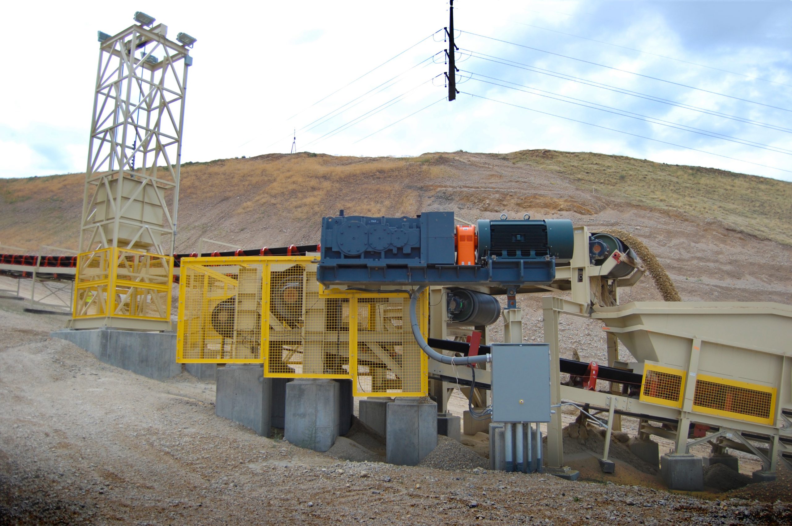
Pulley selection
The standardization of pulleys lends itself to the ease of choosing the correct pulley for a given application. The most commonly used pulley is the standard steel pulley. Plain steel drum pulleys are best used in dry clean environments where traction is not critical, and when no foreign material is present on the return belt.
Conveyor pulleys may also be covered with rubber, fabric or other material (lagging). Lagging on a drive pulley provides an increase in the friction between the belt and the pulley. Lagging is also used to reduce abrasive wear to the pulley face and create a self-cleaning action on the pulley surface. Plain rubber lagging on drum pulleys is typically used in snub applications where traction is not critical. Replaceable lagging is also available. The lagging strips are welded to the face of the pulley, and can easily be replaced in the field.
Wing pulleys are typically used in tail pulley applications to reduce material buildup between the belt and pulley; trapped materials fall through the paddle-like formations. Lagged winged pulleys are used in applications with abrasive material present on the return side of the belt. It is natural under these conditions for the wing tips to wear prematurely. The rubber lagging will add life.
Conventional wing pulleys are particularly susceptible to material buildup, wing bending, and noise and vibration during operation. Belts and tail pulleys are subject to damage and failures when fugitive material becomes entrapped between the belt and the tail pulley. If the material is not removed, several issues can occur:
- Degraded material can be carried between the belt and the pulley, causing excess wear and tear on the belt, as well as belt slippage and mistracking.
- Large entrapped material with sharp edges can create an uneven belt surface and can puncture, gouge or rip the belt.
- Entrapped material in the pulley can damage the pulley face, bend the wings, or causes pulley or belt failure.
Removing material buildup from the pulley or repairing or replacing pulleys and belts results in significant downtime and maintenance costs.
In 2007, Superior engineered new v-shaped wing pulley to prevent material buildup and belt damage while greatly minimizing noise and vibration during operation. When compared to the conventional wing pulley, the v-shaped design delivers numerous time-and -money saving advantages over that of traditional choices.
Shafting is commonly considered to be a part of the pulley assembly since the strength and rigidity of the assembly depends on both of these components. When choosing shaft diameter, it is important to consider both the shaft diameter required for strength and shaft diameter required for deflection. Depending on the pulley assembly, either strength or deflection may be the deciding factor of shaft diameter.
Scraper selection
Carryback, fugitive material that sticks to the belt after passing over the head pulley, subsequently creates fugitive material piles along the conveyor’s underside. It is a costly problem, considering that many maintenance hours are spent cleaning these piles.
Belt cleaners are used to correct carryback, usually via a wiper, blade or scraper device mounted near the discharge (head) pulley. A common type of belt cleaner is the pre-cleaner, often referred to as the primary cleaner; it functions by scraping off most carryback, leaving only a thin layer of fines on the belt. The pre-cleaner is mounted on the face of the head pulley just below the discharge trajectory. This allows material scraped from the belt to fall with the discharge materials.
Multiple cleaner systems are the preferred method for eliminating carryback. The multiple systems consist of a pre-cleaner and one or more secondary cleaners. In addition to the improvement in belt cleaning, multiple belt cleaner systems increase the time interval between scheduled maintenance. Belt cleaners should be positioned as close to the head end as possible.
Secondary cleaners are designed to remove the thin layer of fines left by the pre cleaner. It’s best to place the secondary cleaner in contact with the belt while it is still against the head pulley. This enables the cleaner to scrape against a firm surface. If you require both primary and secondary cleaning, but your conveyor is not designed to accommodate the secondary cleaner, look for technology that combines primary and secondary blades with one shared mounting pole.
There are several types of non-traditional belt cleaners to eliminate carryback; the brush type can be driven by the pulley motion or motorized. This type is effective on dry materials, as the brush bristles sweep the belt clean. The disadvantage to brush-type cleaners is the potential for build-up.
Pneumatic type belt cleaners send a stream of air across the pullet face to blow off carryback. They are best utilized when moving dry materials. The disadvantages are the expense of a continual air stream and creation of dust.
There are two styles of wash-type cleaners that use water to clean the belt. The first is a system that sprays a misting of water on the belt in order to make the scraping process easier. The second uses high-pressure to completely remove carryback. These types of cleaning systems create sludge and that can be a problem to remove. They also have the potential for trouble under cold operating conditions.
Return belt cleaner systems, or v-plows, are used to prevent large objects and tramp iron on top of the return belt from damaging conveyor components. A low-pressure mechanical scraping is used to remove the material from the belt.
Take-up selection
Conveyors need take-ups to ensure proper belt tension, which prevents belt slippage and material spillage. They also compensate for belt shrinkage or stretch. The required take-up movement length is determined by the type of mechanism being used to start and stop the conveyor, the frequency of starts and stops with a loaded belt, stretch characteristics of the belt, and running tensions. There are two types of take-up systems, manual and automatic. The manual systems are preferred when an automatic take-up is impractical like operation of short, light conveyors.
Transfer points
A transfer point is any conveyor point where material is loaded onto or unloaded from the conveyor belt; the ideal transfer point would be designed to load the belt in the center and at a uniform rate. They should also reduce impact of the material falling on the belt and maintain a minimum angle of inclination of the belt at the loading point.
The design of discharge chutes and other loading equipment should take these topics into consideration. Other factors such as capacity, size, characteristics of material, speed and belt inclination should also be considered.
Skirtboard systems
Skirtboards keep transfer material on the belt after it leaves the loading chute until it reaches belt speed. They are usually an extension of the loading chute and extend for some distance along the conveyor.
The distance between the skirtboard and the conveyor belt is critical. Skirtboards need to be placed high enough so they never come into contact with the belt; however, the gap between the belt and skirtboards should be as small as allowable. The closer they are together, the easier it is to maintain a seal between them. The gap between the bottom edge of the skirtboard and the belt is usually sealed by a flexible rubber strip attached or clamped to the skirtboard exterior.
Skirtboard length should be 2-3 feet per 100 feet per minute of belt travel. Material should travel at the same speed as the belt by the time it leaves the load area.
Impact systems
Transfer point structures can rapidly deteriorate due to impact from heavy objects or material with sharp edges. Load zone impacts also cause wear and damage to the conveyor belt, weakening its carcass.
To aid in damage prevention, transfer points should be designed to lessen the height of the material drop. There are also devices to reduce impact at transfer points. Impact troughing idlers have rubber-cushioned rollers to absorb impact; beds or cradles can also be positioned under the belt to absorb impact.
Safety systems
Emergency stop switches consist of a pull-cable running alongside the conveyor, connected to a switch approximately every 100 ft. The switch either shuts down the conveyor system or sounds an alarm if the cord is pulled, providing an extra safety device for operators and conveyor maintenance workers. Another safety device important in conveyor design is guarding. Machine guarding provides a safer working environment. Examples include drive guards used to cover v-belt drives, rotating shafts and jackshafts; return roll guards used to guard idlers less than seven feet from the ground; and side guards to prevent access to pinch points and rotating components.
Travis Thooft is chief conveyor engineer for Superior Industries.