Ore mine uses air cannons to unclog chutes.
By Mike Moody, business development manager, Martin Engineering
No matter what type of ore is being extracted from a mine, mucking with front loaders can be accompanied by wet fines that cling to every surface. Once loaded into a hopper or conveyer transfer chute, viscous material can quickly build up on the walls to create bottlenecks, clogging the chute and causing expensive downtime.
Clearing material from hoppers, chutes, bins and vessels can be done using manpower and tools on hand, but safety experts recommend considering a solution that prevents exposing workers to potential hazards. Operators at modern mining sites, such as Eagle Mine in western Marquette County of Michigan’s Upper Peninsula, understand that using specialized equipment reduces worker exposure, offers the safest mode of production and provides the most cost-effective lasting results.
“Safety is a top priority for us,” said mine lead reliability technician Ted Lakomowski. “When we experienced clogging and downtime at the processing mill, our crew naturally swung into action to resolve it, but we immediately sought a safer long-term solution.”
Nickel, Copper Stope Mining
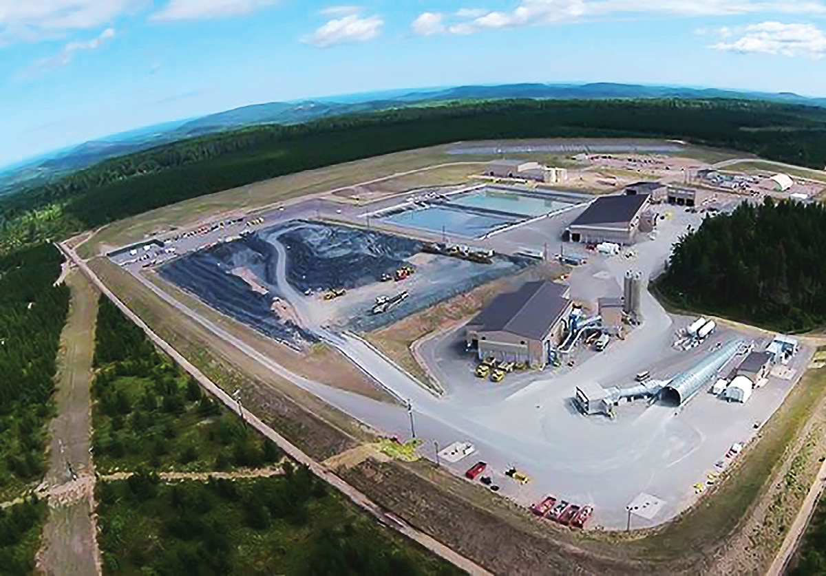
Owned by Toronto, Canada-based but globally focused operator Lundin Mining, the Eagle mine is the only primary nickel mine in the United States, producing 1.5% of the world’s total nickel production. The first operation permitted under Michigan’s Part 632 Non-Ferrous Mineral Mining Law, it opened in 2014 and is expected to produce 360 million pounds of nickel, 295 million pounds of copper and small amounts of other metals over its estimated nine-year lifespan.
The company extracts approximately 2,200 st/pd (2,000 mt/pd) from the underground nickel-copper mine using a bench-and-fill stoping process. Accessed from the surface by specialized underground trucks, the vehicles carry about 100,000-pound (45,400-kilogram) loads through a one-mile (1.6 kilometers) long, 18-foot (5.4-meter) diameter ramp shaft descending into the earth at a 13% grade.
Stoping is a bottom-up method that involves systematically blasting columns of loosened ore that is then mucked by front loaders into trucks and backfilled using cemented and uncemented rockfill.
The mine’s ore is stored in a covered coarse stockpile facility prior to transport by road approximately 65 mi.(105 km) to the Humboldt mill. A former iron ore processing plant, the site was converted and refurbished to accommodate Eagle’s updated processing facility. A three-stage crushing circuit reduces the material to 3/8 inch-minus, then a single stage ball mill grinds it further to sand, where it is mixed into a slurry.
To liberate nickel and other minerals from the waste materials, a refining process of selective flotation is used, mixing the ore with special reagents and agitating it with devices producing air bubbles. As the oxygenated bubbles rise through the heavy slurry at the bottom of the chamber, sulfide particles adhere to the surface and collect as a concentrate containing nickel and copper sulfides at the top of the liquid.
The slurry passes through several stages to also release copper concentrates, along with other trace precious metals. The tailings from the plant are safely impounded sub-aqueously in the decommissioned and restored ore pit from the previous plant.
“The end goal is to leave the stoping columns with no voids and the environment around the working areas better than we found it,” Lakomowski said. “It is Lundin’s mission to constantly assess environmental impact and to work with local communities to seek the most sustainable solutions throughout the lifecycle of mining operations.”
Humidity and Ore Properties
The clogging issues were found in an undersized chute in the Humboldt milling process. Although material was damp when mucked, it was further exposed to rain, snow or summer humidity during transport by truck to the mill.
“The issue was particularly acute in springtime, when it rains excessively,” Lakomowski explained. “At that time, clogging increased to several times per shift.”
During the crushing process, a mesh screen separates the fines from the remaining aggregate, which are fed back through the process. Fines that pass through a screen fall into a wide-mouthed hopper, leading to a chute that narrows to approximately 8 ft. (2.5 m) wide by 2 ft. (0.6 m) high and – after a dead drop of several feet – slopes abruptly in an approximate 45º angle of decline.
This slope slowed the descent of the fine material for a low impact and centered discharge onto a conveyor belt leading to the ore bins. Material buildup began at the hopper and at the discharge slope, but could also occur at virtually any point, blocking the chute.
Beyond the moisture content, the adherent qualities of the raw material also contributed to the accumulation issue. Some nickel-bearing sulfides can display weak magnetic characteristics at room temperature or higher, which may slightly amplify the adherent nature of the material.[1]
Seeking Solutions, Finding Obstacles
Accumulation would stop the entire crushing process approximately three to four times per shift for as long as an hour, blocking input of material all the way back to the ore storage area. The breaks in production and ensuing downtime had an immediate effect on the cost of operation. As soon as the clogging was observed, workers quickly began clearing the obstruction by hitting the side of the chute with mallets and poking at the obstruction with long implements.
Eventually, they attacked the clog with 15 ft. (4.5 m) long air lances from the top of the hopper and bottom of the chute. The method used a tremendous amount of compressed air and diverted manpower from other essential duties. Moreover, air lances caused excessive splash-back of wet material, which was extremely messy and potentially hazardous.
Recognizing the need for a better solution, Eagle first installed a UHMW polymer lining in the chute. Offering a low coefficient of friction, the lining was bolted to the chute wall and acted like a smooth slide for the material to ride down. Unfortunately, it was less effective against the adherent qualities of the material than hoped.
To supplement the lining, Eagle next installed pneumatic vibrators onto the vessel wall intended to agitate the adhered material and promote its descent down the chute slope. The impacting action was meant to create a vibratory wave across the vessel surface. Instead, the fact that the polymer lining was bolted to the vessel caused it to muffle the vibration of the units, limiting the force to only the impact zone and not much farther.
Although the solutions reduced clogging slightly, labor was still needed to fully evacuate the material from the chutes.
“We were forced to default back to air lances, but kept on looking for a better solution,” Lakomowski explained. “Having worked with Martin Engineering in the past, we asked them to come in, examine the issue and offer a safe, effective and affordable solution.”
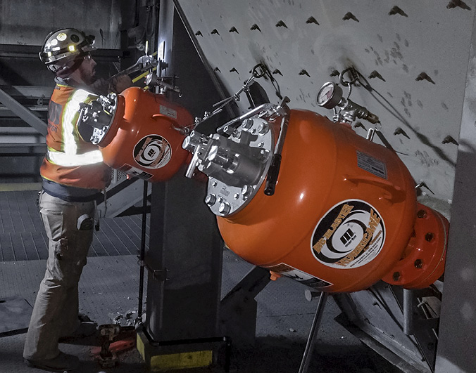
A single worker can perform maintenance on outward facing valves, reducing potential risk. 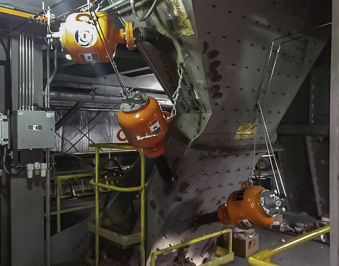
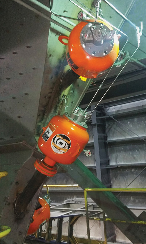
Strategically positioned at a 30º angle, the cannons keep material flowing.
Compressed Air Usage
The technical team at Martin Engineering observed that the previous solutions did not adequately aid the flow of material. The sand-like slurry was still clinging to the surface, creating an abrasive layer that tended to offset the slickness of the UHMW polymer lining, allowing material to build upon itself. The issue was presented at many stages of the process, so a solution was needed throughout the transfer.
“We realized that the air lance solution was only temporary, but was effective in moving material,” said Martin territory manager Jason Haynes. “We proposed installing air cannons at strategic points throughout the chute to dislodge material and aid flow, but managers had some initial reservations.”
Many mining operations require compressed air for some machinery to function, and Eagle is no different. The process of separating nickel and copper from the slurry at the Humboldt facility is dependent on instrument air, which keeps valves operating and the mill drivetrain engaged. Anything which jeopardized compressed air availability and capacity naturally yielded concern for the operation.
“Compressed air is almost a currency here, so we were naturally skeptical of using a solution that impacted pressure,” Lakomowski clarified. “Many in the organization had experience with older air cannon designs and knew the potential drain they could put on a system.”
In the past, large inefficient air cannons could burden a compressed air system and require an excessive amount of energy to develop adequate pressure, push air through the system and retain the pressure during output. According to Lakomowski, compressed air has an estimated energy exchange rate of 8:1. This means that it costs 8x more energy to power a device with compressed air than using direct power, causing the power drain to be more expensive.
Air Cannons
Air cannon technology uses compressed air to promote proper flow by quickly filling a tank, delivering a powerful shot to the vessel wall in the direction of the moving cargo, dislodging adhered material and introducing it back into the stream.
After Haynes detailed the low impact that new air cannon technology has on compressed air systems, Lakomowski advocated for the initial installation of five 35-liter (9.25-gallon) Martin Hurricane Air Cannons, followed by two more placed in essential spots in the chute. All of the tanks were accompanied by a 4-inch (101-mm) pipe assembly ending in fan jet nozzles.
Offering more force output than designs double their size with considerably less air consumption, the compact Hurricane Air Cannon tanks measure only 16 in. (406 mm) in diameter, 24.92 in. (633 mm) long, and weigh 78 lbs. (35 kg) each. The units fire a shot of air at up to 120 psi (8.27 bar) through the fan jet nozzle, which is 4 in. wide where it connects with the pipe assembly then spreads to 12 in. (304 mm) at the exit point, distributing the airstream across the surface of the wall.
Designed with safety and low maintenance in mind, the cannons feature a centrally located outward-facing valve assembly that can be replaced within minutes, without the need to remove the tank from the vessel. To prevent the risk of unintentional firing due to drops in pressure, the innovative valve design requires a positive signal from the solenoid in the form of an air pulse to trigger release.
Installation and Testing
For access inside the chute, installers first removed the lining and cut holes to fit the air cannon pipe assemblies, which pointed at a 30º angle in the direction of the cargo stream. Beginning with five cannons, one unit was placed at the area where material discharged into the hopper, two others were positioned at the hopper slope where the most accumulation was observed and two more cannons were placed along the drop chute. These used straight pipe nozzles to shoot air across the vessel to dislodge adhered material and promote flow.
“The initial installation reduced the amount of downtime, but testing showed it did not cover enough area to fully evacuate adhered material,” said Haynes. “More accumulation built up in transition sections of the hopper and discharge slope than initially thought. So, we installed one more cannon at the top of the hopper and one at the bottom of the chute where it discharged. We also added the fan jet nozzles to the pipe assemblies to cover more area, and that did the trick.”
A single solenoid box was installed to control up to 10 cannons and was safely located away from the firing area. Connected to a distributed control system (DCS) in a central control room, operators can monitor and adjust firing sequences from a remote location or fire the cannons directly from the solenoid box without needing to interact with the cannons.
Results
Operating on a regular firing schedule of every one to 10 minutes, readjusted for production volume, time of year and moisture level, revealed the seven cannon configuration reduced clogging issues and downtime. This significantly lowered the risk to operators and reduced the cost of operation.
“When I did the cost assessment, I was surprised to discover that there was a 1000 percent savings in using the air cannons over the air lances,” Lakomowski said. “It’s a significantly lower effect on our system than initially predicted, and managers are very happy about that.”
The project also improved safety, as workers spent less time diverted from other assignments to use air lances or create vibration by beating on the vessel walls. By being able to perform maintenance on wear parts like valves from the outside of the cannon without tank removal, upkeep can be safely performed by a single technician with no heavy lifting involved.
“Just from a safety aspect, this solution has paid for itself,” Lakomowski concluded. “The Martin Engineering team was easy to work with, and they were cognizant of our budget restrictions. Overall, this was a successful project.”
References
[1] Taylor, John; Wise, Edmund: “Nickel processing – Extracting and Refining – From Sulfide Ores”; Encyclopedia Britannica. Sept. 5th, 2003. https://www.britannica.com/technology/nickel-processing