Transfer points are where wear, impact, spillage, and carryback all converge. Getting them right is essential, but that can be more complicated than most operations realize.
by Jonathan Rowland
Imagine we are standing at a transfer point. It is here that the full complexity of bulk materials handling asserts itself. Impact loads stress the belt. Turbulent material streams push against skirting systems. Fines escape. Carryback collects in hard-to-clean places. And when tonnages are pushed (as they almost always are, sooner or later), what was working well yesterday may no longer be doing so today.
As we watch material thunder onto the belt, the first lesson is simple. Transfer points are an organism: a system of interdependent elements that work together to produce a result, for good or bad:
- A chute that shapes and directs the material stream.
- Impact protection that absorbs the energy of the falling load.
- Skirting and sealing systems that contain it.
- The belt support that keeps the sealing surface stable.
- The tracking system that keeps the belt where it should be.
- Cleaners that reduce carryback.
- The splice that holds the belt together under sustained dynamic stress.
Achieving optimal performance depends on getting all these elements right. So, without further ado, let us dive in and build a picture of what a well-engineered transfer point looks like and what operators need to know to protect their belts, their loads, and their bottom line.
FUNDAMENTALS OF TRANSFER POINT DESIGN
According to Dan Baxter at FEECO International, transfer point design can be framed around a few core principles that apply whether an operation is building new or upgrading existing infrastructure.
The first, and arguably most consequential, is minimizing drop height. Every meter of additional fall height translates into greater impact loading on the belt and greater turbulence in the material stream – both of which accelerate wear and increase the likelihood of spillage. This means that, where a vertical chute can be repositioned at an angle so material slides rather than drops, it should be.
Controlled feeding follows from this. Feed chute geometry should be engineered to introduce material to the belt as gently as possible. A consistent, regulated flow is the aim, rather than surges that repeatedly overload the impact zone. In high-volume surface mining applications, providing adequate belt support is essential to avoid belt sagging, including the use of impact idlers or impact beds (or cradles) that absorb excess energy and minimize the risk of belt damage.
Belt cleanliness rounds out the design picture. When handling ore containing clay or high moisture, carryback from the head pulley can cause significant downstream problems. Baxter recommends proper belt-cleaning measures at the head pulley, including dual cleaners in especially challenging conditions, a theme we will return to later.
STOP THE SPILL
Spillage at transfer points is usually the cumulative effect of several containment elements operating below standard, Andrew Collier of ASGCO Manufacturing explained. Effective containment thus requires managing the entire load zone as an integrated system. “Effective containment depends on coordination between chute design, belt support, and sealing elements,” he said. “When these components are engineered and maintained as a unified system, operators can significantly reduce spillage, minimize cleanup requirements, and extend the life of the conveyor and its components.”
The starting point when tackling spillage is the trajectory of the material stream as it exits the chute. When material lands centrally on the belt and with minimal turbulence, it establishes the best conditions for effective containment. Off-center loading, however, creates side forces that push against skirting seals and contribute to belt mistracking and premature wear: problems that no amount of skirting adjustment can fully compensate for. A chute design that centers the material and reduces impact turbulence is thus the prerequisite for everything that follows.
With the material stream controlled, Collier also emphasized belt support as a critical factor. Inadequate support allows the belt to sag between idlers, creating gaps between the belt surface and the skirting system, which allows material to escape. Even a correctly specified seal cannot function if the sealing surface is unstable. Impact beds in the load zone are therefore critical to a consistent belt profile, providing skirting systems with a solid surface to work against. Collier also recommended avoiding load-zone installation in the troughing transition area, where the belt profile changes, and leaks are more likely.
Skirting systems must then use that stable belt surface to deliver consistent sealing pressure and contain the material. Materials that can maintain contact without generating excessive friction, such as ORG rubber, help extend service intervals. Regular inspection and adjustment are also essential: worn skirting that has lost contact with the belt surface will allow dust to escape even before visible spillage occurs.
Beyond skirting, dust pick-off points at the load zone provide a further line of defense, capturing fugitive dust before it escapes the enclosure and allowing it to be reintegrated into the material stream rather than lost to the surrounding area.
IMPACT PROTECTION
When it comes to impact beds, technology has had to keep pace with the demands of modern surface mining operations, such as higher tonnages, larger lump sizes, and greater drop heights than the equipment was originally designed for, said Geoff Stoll at Richwood, who outlined the parameters that should drive impact protection selection.
The core calculation is kinetic energy: a function of lump size, material density, and drop height. For example, a 12-inch lump falling six feet delivers a fundamentally different load than 2-in.-minus material falling three feet. The latter will behave as a homogeneous stream, while the former presents concentrated point loads that require a very different engineering response. Kinetic energy determines whether a standard impact system is adequate or whether a heavy-duty solution is required.
A second consideration in impact zone design is the chute geometry and impact trajectory. In addition to affecting containment system design, off-center loading influences the impact bed location. Changes to the chute may thus be needed to optimize loading and protect the belt. Meanwhile, horsepower requirements are a factor Stoll flagged as frequently underestimated: impact beds and idlers impose more friction than standard carry idlers and thus require higher horsepower to maintain continuous operations. Most systems have sufficient headroom to overcome the added drag, but it should be verified.
Finally, maintenance access matters: systems that allow segment and idler replacement without raising the belt reduce downtime and encourage timely maintenance, which in turn protects the belt and extends system life.
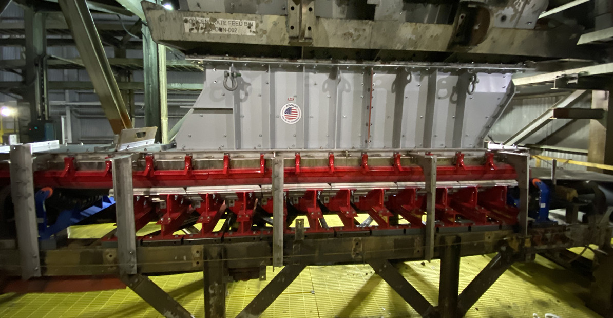
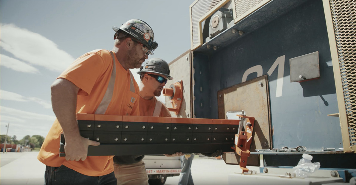
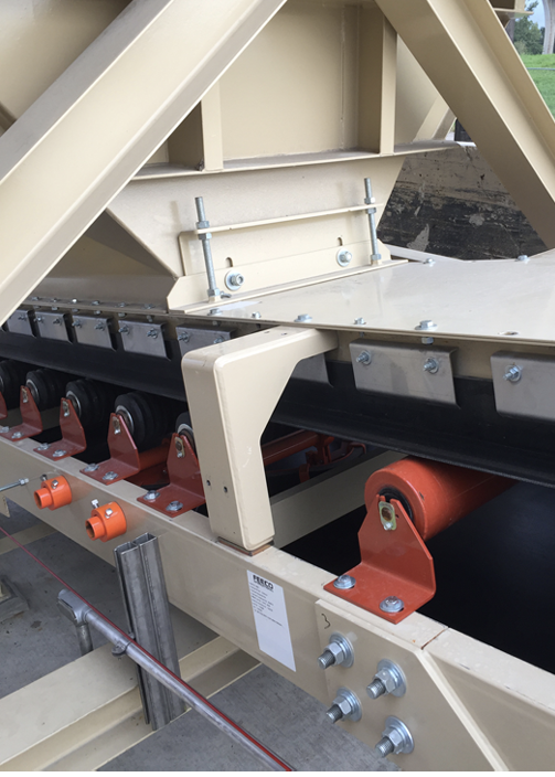
Photo: ASGCO Manufacturing
ENGINEERING THE CONSUMABLE
Impact bars and chute liners occupy an unusual position in the transfer point system: they are, by design, consumable, yet their specifications and replacements often receive less attention than those of longer-lived components. According to Sean Herdrick at UMP Tech, however, they should be treated as engineered wear systems, specified to match actual conditions, monitored systematically, and replaced on a planned rather than reactive basis. Key selection criteria include drop height and lump size, throughput, and belt speed.
When it comes to material selection, the choice must reflect the dominant wear mechanism at each zone of the chute. High-impact zones – characterized by large lumps and significant drop height – require impact bars with energy-absorbing, resilient cores, durable sliding caps, and sufficient thickness to protect the belt carcass. Sliding and abrasion zones, where fines and high belt speeds pose the primary challenge, benefit from harder, antistatic surfaces. Wet or sticky materials require low-friction options to maintain material flow, while corrosive environments demand chemical resistance. Herdrick’s point is that a single specification across the entire chute is unlikely to be optimal: impact, transition and sliding areas often require different formulations.
The replacement program should be built around the wear indicators that manufacturers provide, such as layered color systems, molded depth indicators, exposed markers, and cap-thickness indicators. These are planning tools: visibility of a mid-layer color should prompt scheduling of replacement during the next planned shutdown, well before a failure-driven response becomes necessary.
The underlying data discipline is straightforward: establish baseline measurements at installation, conduct regular inspections tied to tonnage or operating hours, document wear rates, and replace at defined thresholds – typically 70% to 80% consumed. By tracking wear against production metrics, operators can estimate remaining life and align replacements with maintenance windows rather than around unplanned stoppages.
BELT MISTRACKING: DIAGNOSING A SYSTEMIC PROBLEM
Belt mistracking at a transfer point is frequently a symptom of conditions elsewhere in the system rather than a localized problem. Attempts to correct it at the point of visible deviation rather than at its source will tend to fail, as Jerad Heitzler at Martin Engineering explained. According to Heitzler, effectively diagnosing the issue means understanding where and how tension varies along the conveyor.
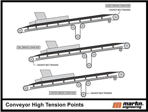
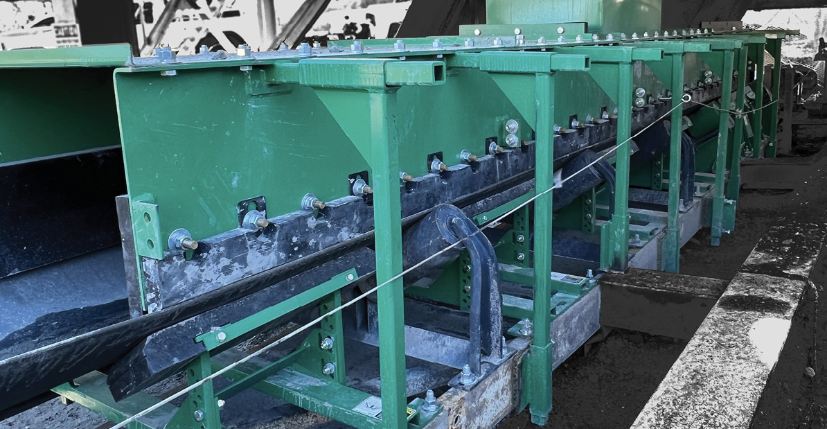
Photo: Martin Engineering
The starting point is the low-tension zone, typically at the point of departure from the drive pulley. Adjustments made in low-tension areas have the most significant impact on correcting the belt’s path; high-tension areas (Figure 1) around the drive pulley require more care. The take-up pulley tension should be verified against current belt specifications and capacity ratings, as inadequate tensioning causes the belt to cup, eventually leading to deviation.
When inspecting for mistracking, Heitzler’s guidance is to track the belt’s path until the visible deviation is identified, then look upstream for the cause. The belt’s condition at any given point is primarily shaped by the idlers and components it has already passed, not those downstream. “Corrective action should focus on points the belt has passed before the visible mistracking area,” he said. “Adjustments to an idler typically produce their most significant corrective effect within a five- to eight-meter range downstream.”
Heitzler also highlighted the use of automated tracking systems that can make micro-adjustments in real time, using sensing arms that detect minor changes in belt path and proportionally adjust the steering assembly. The value of these systems is not just correction but the speed of correction: by adjusting the belt immediately, material is more likely to return to center rather than continue riding the drift.
CARRYBACK AND BELT CLEANING
Carryback is one of the more insidious problems at a transfer point: it is a source of material loss, a driver of wear on belts and return idlers, and a housekeeping and safety issue. And, as with mistracking, it is a challenge that, according to Heitzler, often relates to systemic issues in transfer point design rather than a local problem.
The connection runs through the center of the belt. Most primary urethane cleaning blades are specified to span the width of the material stream rather than the full belt width. This is because blade-to-belt friction increases power consumption and accelerates belt wear. However, if the material stream does not hit the head pulley centrally – because the belt is mistracking or the load is off-center – a portion of the stream misses the blade and remains on the belt. It then migrates along the entire return run, dropping spillage and generating dust.
The cleaning system must be designed around this reality. Heitzler’s general guidance for bulk handling is that most applications require a primary blade at the head pulley, followed by a secondary or tertiary cleaner. Cleaning system design should account for cleaner design, tensioner and mounting requirements, the structural features of the conveyor (beams, bearings and drives), and the practicalities of maintenance. A tensioning device should deliver consistent blade-to-belt pressure throughout the blade’s service life, and re-tensioning should be possible without tools and without requiring more than one service worker.
But it is also important to set realistic expectations: “Bulk handling is a dirty business,” Heitzler concluded. “In practical operations, satisfactory belt-cleaning performance is about 90%, leaving fugitive material cleanup to a weekly schedule, while minimizing dust and avoiding compromises to safety or productivity.”
THE SPLICE UNDER STRESS
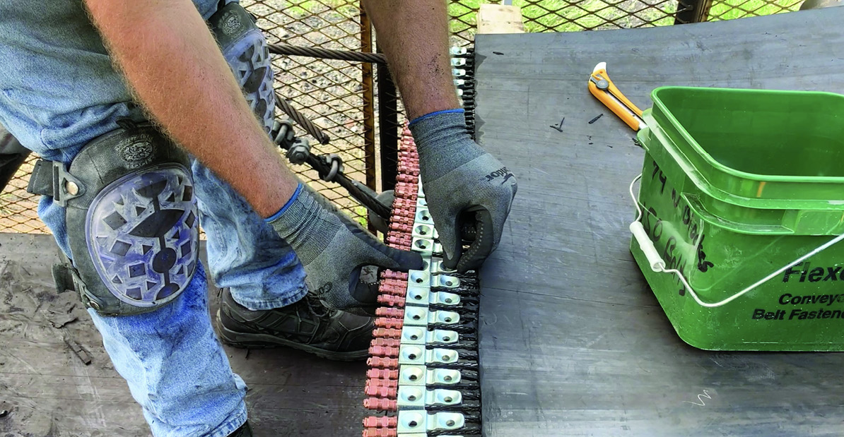
The splice is the point in the belt most exposed to the dynamic forces generated at the transfer point. Under poor transfer point conditions, it is also the most likely to fail. According to Franklin Moore and Russ Heintz, both at Flexco, splice selection is best framed within a conversation that centers on what happens around the splice and how well the transfer point is engineered in the first place.
Both vulcanized and mechanical splices can perform effectively in high-tension applications. Vulcanized splices require significant downtime to install and specialized technicians to complete, which makes them difficult to manage in operations where belt availability is critical. Mechanical belt fasteners offer faster installation, easier field repair, and the ability to return a belt to service quickly. Belt speed, tension requirements, material characteristics, and the operating environment should drive the selection.
Regardless of the method used, overloaded or poorly supported transfer points shorten splice life, which takes us back to load zone design. Proper belt support, effective skirting, aligned tracking systems, and well-positioned impact beds all reduce the forces acting on the splice as material hits the belt. The splice selection conversation, in other words, should be preceded by a transfer point design conversation.
Warning signs differ substantially between splice types, and this is one area where mechanical fasteners have a clear practical advantage. As Moore and Heintz pointed out, fastener wear is visible and progressive, allowing planned maintenance before a failure occurs. However, vulcanized splices are harder to assess visually: degradation often happens internally, and failure can come with little warning. For operations with long belt inspection intervals or difficult access, this difference in inspectability warrants careful consideration.
WHEN TONNAGE INCREASES
Capacity increases are a routine feature of surface mining operations, and transfer points are usually where the consequences first show up. Richwood’s Geoff Stoll offers some direct advice: review before you increase, not after. Once tonnage has been pushed to its new maximum, catching up with the engineering implications becomes significantly more difficult and potentially more dangerous.
The scope of that review should be broad. An increase in tonnage will affect transfer chutes, impact beds, material containment, belt tension, horsepower requirements, and structural support. Stoll emphasizes that the structural review is the element most often overlooked – and potentially the most serious. Increasing the load on a system not designed for it reduces the safety factor from the original design parameters. “An increase in tonnage will affect transfer chutes, impact beds, material containment, belt tension, horsepower requirements, and structural support,” he said. “All elements of the transfer system need to be evaluated.”
For impact beds specifically, operators should understand any changes in belt width, belt speed, material size, drop height, and throughput in tons per hour, and consult the OEM for a review of the current system. Material containment systems may need to be replaced or extended in length and height. Meanwhile, chutes must be evaluated for liner wear, material throughput, impact location, and material discharge, with liners potentially upgraded to accommodate the new conditions.
THE CASE FOR A SYSTEMS VIEW
The consistent message from all our experts is clear: transfer point performance is a product of the system, not of any individual component. Chute design sets the conditions for everything that follows. Belt support determines whether skirting systems can function. Impact protection must be specified for the actual energy loads. Consumables need to be monitored and replaced on a planned basis. Mistracking is a diagnostic challenge, not a localized fix. Belt cleaning performance is bound by how well the rest of the system is working. And the splice, under all of this, can only perform as well as the conditions around it allow.
When tonnage increases – as it will – every one of these elements needs to be re-evaluated. The operators who treat that re-evaluation as a routine part of capacity planning, rather than a response to the first failure, are the ones most likely to keep their belts running and their loads where they belong.
MEET THE EXPERTS
Dan Baxter handles material handling sales at FEECO International.
Andrew Collier is the engineering manager at ASGCO Manufacturing.
Russ Heintz is a senior training and technical specialist at Flexco.
Jerad Heitzler is the training manager at Martin Engineering.
Sean Herdrick is head of sales and marketing at UMP.
Franklin Moore is the heavy-duty mechanical belt fastener product manager at Flexco.
Geoff Stoll is the engineering manager at Richwood.