The ins and outs of conveyor transfer distance, angle and overlap: An expert viewpoint from one of those who trains the trainers.
![]()
Surface conveying can reach long distances with several transfers in less-than-optimal weather. Mine operators are discovering the ongoing cost of labor, gas and insurance for traditional vehicle ground transport far exceeds the upfront cost of conveying. However, inspecting and maintaining these outdoor systems are accompanied by their own challenges that are best remedied through engineering design.
Efficiency is achieved when the conveyor transfer point can sustain production levels until the next scheduled shutdown without excessive hours of labor for cleaning up spillage, unscheduled downtime for maintenance of broken components and billowing clouds of dust.
The length of the conveyor transfer point varies according to the needs of the application and the allowable physical space. Consisting of a loading zone, a stilling zone and a settling zone, the general rule is that longer settling zones are better. However, in an attempt to save money, operators choose shorter transfer point designs just to find out that length is not the only thing it falls short of. It also fails to allow for settling dust, handle production demands, or – most importantly – improve workplace safety.
In-line transition
In an ideal world, all belt-to-belt transfers would be in-line and all the discharging and receiving belts would run in the same direction. In-line transfers reduce the length of the conveyor when drive power or tension is insufficient for a single belt. These transitions are often necessary to extend the length of the conveyor system or to accommodate mechanisms to blend, crush or separate the material. Transitioning in this manner also makes it relatively easy to place the material on the receiving belt with the load moving in the direction of the belt, reducing unnecessary wear and spillage.
Most inline transfers allow for sufficient belt overlap to avoid “loading on the transition;” it may seem confusing because this doesn’t mean the conveyor-to-conveyor transition, but instead, it means the belt trough angle transition where the belt goes from flat against the tail pulley to curving into a full trough angle equal to the angle of the cradles and idlers. Loading on the transition area is often an attempt by designers to reduce costs by saving a few meters of conveyor length. It is recognized that this practice creates numerous problems in loading, sealing and belt wear, and should be avoided.
If the belt has not fully transitioned into the trough angle, then the skirtboard and tail box are ineffective at sealing the loading zone. Due to the force and turbulence of the material hitting the belt, fugitive spillage and dust pour out of the openings. The dust permeates the area making visibility and maintenance difficult and may lead to a workplace violation. Spillage piles around the tail pulley, potentially fouling the pulley face, resulting in abrasive damage to the unprotected side of the belt and lowering its operational life. If spillage obstructs walkways and access, this too could pose a workplace violation due to slips, trips and falls, which consistently rank at the top of the list of the most common workplace injuries.
Non-linear transition
Typically, a conveyor transition denotes a change in the direction of the cargo flow as one conveyor loads onto another, also known as a “non-linear transfer.” This may be required to divert material toward stockpiles or for separating the material.
Problems associated with non-linear transfer points include a difficulty in maintaining the material’s proper speed, trajectory, and angle; problems controlling dust and spillage; and issues of increased wear on (and the resulting higher cost for replacement of) transfer-point components.
If material is loaded on the belt in a direction that is not in line with the direction of the receiving belt, wear patterns may become visible on the inside of the chute. Corresponding to the splash pattern of course cargo as it bounces off the inside of the chute, the wear liner may also show increased deterioration on the area where the material adjusts to the direction and speed of the receiving belt. Ricocheting movement of the material within the transfer chute also accelerates wear on the skirtboard, belt and sealing systems.
How loading can cause mistracking
The force of the off-centered loading material may cause the belt to drift as the weight of the cargo pushes it out from under the skirting on one side. This allows the skirtboard to drop down, preventing the belt from returning to its centered position. The belt will attempt to return to its center as material loading changes, forcing the belt into contact with the sealing strip and cutting through the strip, resulting in substantial spillage opportunities.
If a significant weight remains on one side of the belt, it could cause tracking issues down the length of the system, leading to spillage, idler fouling and damage at the discharge zone. Fortunately, a number of strategies and components can be employed to guide the flow of material into the desired direction of travel and load it onto the center of the receiving belt.
Not providing enough overlap of the conveyors is a common mistake that results in mistracking. This leads to a loading on the transition situation, and in some cases, does not allow enough room for installing belt cleaners. Without attention to proper conveyor design, including sufficient overlap, the operation is burdened with a conveyor that will have excessive downtime and a higher cost of operation.
Conveyor discharge trajectory
On a conveyor transfer system, to reduce the load absorption that can damage the belt and dust emissions caused by turbulence, drop height should be kept at a minimum. This is best accomplished by controlling the trajectory of the material. The trajectory is the path the bulk material takes as it is discharged from the delivery conveyor, which is affected by the speed of the belt, the angle of inclination of the discharging belt and the profile of the material on the belt.
The manual, “Belt Conveyors for Bulk Materials: Sixth Edition,” released by the Conveyor Equipment Manufacturers Association (CEMA), maps the procedure to determine a constant trajectory path.
“To plot the trajectory, a tangent line is drawn from the point at which the material leaves the pulley. At regular time intervals along this tangent line, vertical lines are projected down to fall distances. A curve is then drawn through these points to produce the centroid trajectory. The upper and lower trajectory limits can also be plotted by offsetting from the centroidal curve the distance to the belt and to the load heigh,” it said.
The most common mistake made at this stage of design is developing an initial material trajectory that fails to consider the effects of friction when plotting subsequent reflections of the material stream from the transfer chute walls. Modern transfer-chute designs control the stream of bulk material and do not allow it to free-fall from the discharge onto the receiving belt. With this controlled approach, the designer assumes the material cross-section does not fan out or open up significantly. If drop heights are minimized, then material degradation, dust creation and wear on the receiving belt are minimized.
This approach requires some knowledge of the friction values between the bulk material and transfer chute materials. To assess the effects of changing properties, such as the coefficient of friction, designers should consider using the Discrete Element Modeling (DEM) method. There are several DEM software packages on the market designed for this purpose.
Transfer chute, loading zone redesign
Many conventional transfer-chute designs have the trajectory plotted as a starting point where the material stream will first impact the head chute wall. From there, the material stream is assumed to be reflected from other surfaces of the chute wall toward the receiving belt.
Engineered hood and spoon designs use gravity to maintain material flow speed but may require greater drop heights. A spoon configuration provides several benefits that should be considered as part of the original design or as part of the requirement of a future retrofit. Some of the benefits of a spoon design are centered loading for less mistracking; reduced impact for less belt and idler damage; less splash for longer wear liner and skirtboard life; and considerably less turbulence leading to dust and spillage.
Modular transfer points
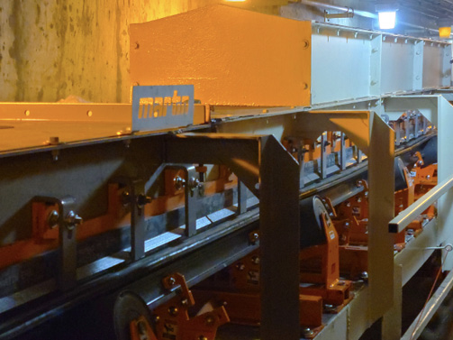
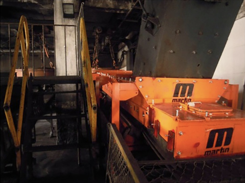
As important as the trajectory of the material is, the receiving belt needs to be housed in a sealed and well-designed environment. Martin Engineering developed a Modular Transfer Point Kit that is adaptable to the needs of bulk handlers of almost every industry. The kit is a heavy-duty horizontal enclosure for the loading zone which includes a loading zone, settling zone, or stilling zone.
The transfer point system accommodates belt widths of 18-72 inches (450-1800 mm) and an internal chute width of 9-59 in. (228-1498 mm). Each modular section is either 4 feet (1.21 meters) or 6 ft. (1.82 m) long and constructed of mild steel, 304 stainless steel or 316 stainless steel with a thickness of 0.25 in. (6.35 mm), 0.5 in. (12.7 mm), or 0.75 (19.05 mm) to accommodate a wide variety of materials and conditions.
Once the kit is built, a series of integrated components such as impact cradles, slider cradles, dust curtains, external wear liners, and self-adjusting or dual-seal skirting can accompany the system to optimize efficiency, safety and maintenance. These components have been meticulously engineered and field-tested to provide optimum results.
Conclusion
The bulk handling environment is punishing on equipment and slight changes in the throughput can have unpredictable consequences. The dynamics of conveyor transitions can depend on changes in weather, material and production demands. To prevent dust emissions and spillage, conveyor transfers require a series of well-engineered components working in tandem to keep the environment sealed, however, they should also be graded above the existing production environment to accommodate these changes. Experts recommend that designers of conveyor transfers consider ease of maintenance, safety and logistics in their design by choosing a single reputable manufacturer for all of the integrated components.
About the author: Jerad Heitzler is Martin Engineering’s Training Manager. As program manager and lead instructor for Martin Engineering’s Foundations Training Workshops, he is a leader in helping the industry learn how to make the handling of bulk materials cleaner, safer, and more productive. He has been with Martin since 2006.